Home › Forums › Products › Stompboxes › Cheap DIY Midi Controller
- This topic is empty.
-
AuthorPosts
-
-
January 8, 2020 at 7:17 pm #115691
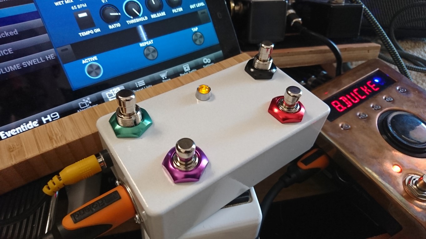
Hey does anyone want to DIY a cheap midi controller?
Here it is.
It is an array of footswitches (up to 11?) that can all send a PC or CC message. I have it set up so pins 2-9 send PC messages 2-9, and pins 10-12 send CC toggles on #16, 17, and 18.
I would set this up with 1-7 switches calling presets (or tuner or Bypass) using the PC pins, along with a CC button for the hotswitch or some other CC value you might like.
PARTS NEEDED:
(1) An enclosure. $5-10
(some) footswitches, momentary, NO $3/each
(1)An Arduino NANO clone – $4.00
(1) a power jack. – $1
(1) midi connector (or you could scavenge a wire and direct-wire it) ($2.00)
(1) 220Ohm 1/4watt resistor – $0.25
(1) midi cable
TOOLS NEEDED:
A Soldering Iron
A drill
A few hours time.
I wont go through the construction too detailed.. I dint actually build one of these. I just breadboarded it.
But, you drill out the enclosure for your switches, your power jack and your MIDI jack.
Then wire it like so:
PC Firing Footswitches
Pins 2-9 on one side, Ground on the other
CC Firing Switches
Pins 10-12 on one side, ground on the other
Ardruino TO MIDI
TX to 220Ohm Resistor to MIDI pin 4
Ground to PIN 3
5V OUtput from Ardruino to Pin 5
Power Supply
Postive to VIN on Arduino
Ground to Ground
Here is the code:
//midi.controller for eventide H9
//by Cameron Newell @the.nw.enterprise, http://thenorthwestenterprise.com/
//Library Source https://github.com/tttapa/Control-Surface
//Built for Ardruino NANO
#include
// Instantiate a MIDI interface
//USBDebugMIDI_Interface usbmidi(115200); // for serial monitor in ide
HardwareSerialMIDI_Interface serialmidi = {Serial, MIDI_BAUD}; //for normal operation
/* Instantiate PCButtons that read the inputs from a push button and sends out
a MIDI Program Change message when they are pressed.
Ex: pcBtn = {**PHYSICALPIN**, {MIDI_PC::**NAMEHERE**, CHANNEL_#},};
Must use PC name, reference here https://tttapa.github.io/Control-Surface-doc/Doxygen/da/da6/namespaceMIDI__PC.html
My setup matches PC to PIN Number
*/
PCButton pcBtn2 = {2, {MIDI_PC::Electric_Grand_Piano, CHANNEL_1},};
PCButton pcBtn3 = {3, {MIDI_PC::HonkyTonk_Piano, CHANNEL_1},};
PCButton pcBtn4 = {4, {MIDI_PC::Electric_Piano_1, CHANNEL_1},};
PCButton pcBtn5 = {5, {MIDI_PC::Electric_Piano_2, CHANNEL_1},};
PCButton pcBtn6 = {6, {MIDI_PC::Harpsichord, CHANNEL_1},};
PCButton pcBtn7 = {7, {MIDI_PC::Clavi, CHANNEL_1},};
PCButton pcBtn8 = {8, {MIDI_PC::Celesta, CHANNEL_1},};
PCButton pcBtn9 = {9, {MIDI_PC::Glockenspiel, CHANNEL_1},};
/*Hotswitch or other cc function
Will fire 127 on press and 0 on release. Use a momentary switch, like the others.
Assicn CC number from here:
https://tttapa.github.io/Control-Surface-doc/Doxygen/d4/dbe/namespaceMIDI__CC.html
https://www.midi.org/specifications-old/item/table-3-control-change-messages-data-bytes-2
Default is cc#16, 17 and 18
*/
CCButton button10 = {10, {MIDI_CC::General_Purpose_Controller_1, CHANNEL_1},};
CCButton button11 = {11, {MIDI_CC::General_Purpose_Controller_2, CHANNEL_1},};
CCButton button12 = {12, {MIDI_CC::General_Purpose_Controller_3, CHANNEL_1},};
void setup() {
Control_Surface.begin(); // Initialize Control Surface
}
void loop() {
Control_Surface.loop(); // Update the Control Surface
}
-
January 9, 2020 at 2:17 pm #153708
And that, my friends, is what you call a great tutorial. Clear, concise, complete.
-
January 9, 2020 at 2:58 pm #153709
I mean, I wish there were more pictures. But this is the only one I took:
-
February 2, 2020 at 3:56 pm #153988
So, I got around to actually making one if these. It was EASY. Anyone can do it… So if you want to learn to solder and get a specific midi controller… This is your joint. When I am back at a computer I will get some pictures up.
-
April 20, 2020 at 5:35 pm #154646
Hey people.
I just built a pretty clean MIDI controller cuz I was bored at home. Here is a detailed writeup with many images.
http://thenorthwestenterprise.com/2020/04/21/another-h9-controller/
YOU GUYS SHOULD BUILD YOUR OWN CONTROLLERS ITS AWESOME
-
June 11, 2020 at 6:21 pm #155111
Wow that picture takes up everything
-
June 16, 2020 at 11:37 pm #155162
Hey people I have made a bunch of these now, and polished up my process a little. Here is a more current How-To.
http://thenorthwestenterprise.com/2020/06/12/a-midi-controller-for-the-eventide-h9-smoothest-yet/
-
July 22, 2020 at 6:19 pm #155389
I’m wanting to give this a shot in building. I have a arduino pro mini. Do I need to change anything in the code. I’m pretty new to the arduino. I have managed to build a switch for my hx stomp using one. It was trial and error but at the end of the day I got it working. Thanks for sharing with everyone.
-
July 22, 2020 at 7:47 pm #155390
It should work without much change in a pro mini!
There is one problem with this code…
The #include line stripped out the library. You need to #include the control surface library, and that line should look like this#include Control_Surface.h
Only with a less than/greater than around the library. These forums strip it out 🙁
On my blog I have cleaner code examples
http://thenorthwestenterprise.com/category/guitars/ -
August 6, 2020 at 8:56 pm #155492
ok people. cleanest codeset yet.
Incluses a spot for an expression pedal (or multiples) as well as a VOLUME BOOST with an LED toggling it’s state. This might break with a Preset switch, but will reset if you hit it a couple times.
Lets see if I can get it to paste correctly. If not, download here:
http://thenorthwestenterprise.com/files/Expanded_Published.ino
//midi.controller for eventide H9//by Cameron Newell @the.nw.enterprise, http://thenorthwestenterprise.com///Library Source https://github.com/tttapa/Control-Surface//Built for Ardruino NANO EVERY#include <Control_Surface.h> // Include the library// Instantiate a MIDI interfaceUSBDebugMIDI_Interface usbmidi(115200); // uncomment this for serial monitor in ide//HardwareSerialMIDI_Interface serialmidi = {Serial1, MIDI_BAUD}; //uncomment this for 5-pin operation- this sends on TX **may need to rename Serial1 vs Serial//USBMIDI_Interface midi; // uncomment for native MIDI over USB//HairlessMIDI_Interface hair (); // uncomment this for Hairless/* Instantiate PCButtons that read the inputs from a push button and sends out a MIDI Program Change message when they are pressed.Ex: = {**PHYSICALPIN**, {**PCHEXVALUE**, CHANNEL_#},};This setup matches PC to PIN Number*/PCButton pcBtn2 = {2, {0x02, CHANNEL_1},}; //PC#2PCButton pcBtn3 = {3, {0x03, CHANNEL_1},}; //PC#3PCButton pcBtn4 = {4, {0x04, CHANNEL_1},}; //PC#4PCButton pcBtn5 = {5, {0x05, CHANNEL_1},}; //PC#5PCButton pcBtn6 = {6, {0x06, CHANNEL_1},}; //PC#6PCButton pcBtn7 = {7, {0x07, CHANNEL_1},}; //PC#7/*Hotswitch or other cc function will fire 127 on press and 0 on release by default. This is overridable. Use a momentary switch, like the others.Assicn CC number from here, precede HEX with 0xEx: = {PHYSICALPIN, {**CCHEXVAL**, CHANNEL_#},{ VALUEWHNPUSHED, VALUEWHENRELEASED }};*/CCButton button08 = {8, {0x10, CHANNEL_1},}; // CC#16CCButton button09 = {9, {0x11, CHANNEL_1},}; // CC#17CCButton button10 = {10, {0x12, CHANNEL_1},}; // CC#18CCButton button11 = {11, {0x13, CHANNEL_1},}; // CC#19/* Instantiate a latched push button that sends MIDI CC messages for a BOOST functionThis still uses a momentary physical switch. Assign to Volume in H9 controlDefault values overriden. Adjust to boost strength preference*/CCButtonLatched boost = {12, {0x07, CHANNEL_1},{ 127, 80 }}; // CC#7 – VOLUME BOOSTconst pin_t BoostLed= {13}; // The LED to display the state of the boost button./* Instantiate an analog input for an Expression pedalThis ia an analog POT with 5v, Ground and Signal. **may jitter***/CCPotentiometer potentiometer = {A0, {0x0B, CHANNEL_1},}; // CC#11, pot wired to pin A0void setup() {Control_Surface.begin(); // Initialize main Control Surface codepinMode(13, OUTPUT); // assign Led pin as output pin}void loop() {Control_Surface.loop(); // Update the main Control SurfacedigitalWrite(BoostLed, boost.getState() ? HIGH : LOW); // Update the LED state to reflect the toggled switch state. Match name of led to name of button}
-
-
AuthorPosts
- You must be logged in to reply to this topic.
